SETI League Technical Manual -- Amplifiers
Copyright © 1998 by H. Paul Shuch, Ph.D.
Executive Director, The SETI League, Inc.
PO Box 555, Little Ferry NJ 07643
email n6tx @ setileague.orgSubmitted for publication in Proceedings of Microwave Update 1998, American Radio Relay League, October 1998.
As more amateurs are building Hydrogen Line radio telescopes, we are beginning to experience interference from strong adjacent out-of-band signals. The most common of these interference sources are Global Positioning System (GPS), Weather Facsimile (WEFAX), and Personal Communications System (PCS) satellites operating in the 1.5 to 1.7 GHz region; cellular telephone equipment operating in the 850 MHz segment; ISM equipment at 915 MHz; and DME/TACAN, air trafic control radar, and airborne transponder signals operating in the 960 to 1215 MHz band. Thus the 1420 MHz hydrogen line is surrounded by interference. Since many of our members are using an additional gain block after their low noise preamplifiers, it seems desirable to incorporate some extra selectivity into these buffer amplifiers. Hence, the AmpliFilter design described here.
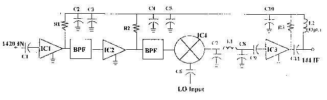
As it happens, most of the work of designing a two-stage hydrogen line preamplifier with six poles of bandpass filtering has already been done for us. Figure 1 below shows the block diagram of the SETI League hydrogen line downconverter, now being produced commercially by Down East Microwave. Note that, in addition to a mixer, IF filter and IF amplifer (the right-hand half of the schematic), the converter contains both gain and considerable filtering at 1420 MHz. And the converter printed circuit board is offered for sale by DEM at a most reasonable cost, permitting us to build up just the necessary gain and filtering stages on an existing board.
|
Schematic of the Down East Microwave model 1420-144 RX downconverter. The left-had four blocks form the basis for the AmpliFilter module. |
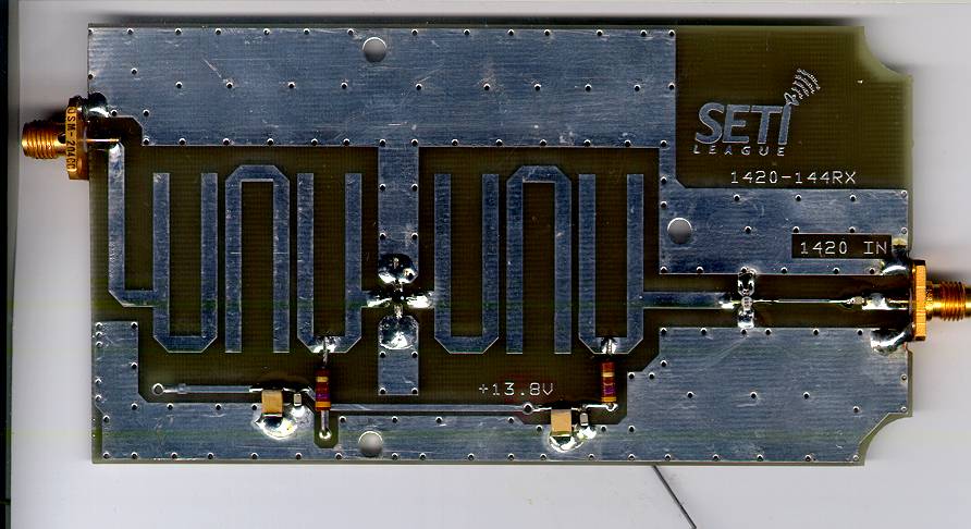
Figure 2 below shows the printed circuit board for the DEM 1420-144 RX converter. The complete converter kit actually contains two circuit boards, the second being the local oscillator chain. It is the board shown below which we are interested in for this project.
With the board oriented as shown, the left-hand 5/8 inch of the circuit board contains the traces for mounting the mixer, IF filter, and IF amplifier. Trim off this portion of the board with tin snips, where indicated with a red vertical line in Figure 2. What remains on the board are its 1420 MHz amplifier and filter stages, and an output microstrip (formerly going in to the mixer) to which an output connector may be attached.
|
SETI League photo |
For the prototype AmpliFilter, I attached an SMA female connector as an end-launcher off the output microstrip, seen at left of Figure 3 below. The entire component count for this assembly consists of two SMA connectors, two monolithic microwave integrated circuit (MMIC) amplifiers, two carbon composition resistors, and five chip capacitors. Everything else is already etched on the printed circuit board, as shown in the photos.
You can adjust the gain and dynamic range of the assembly to suit your individual station requirements. Simply select the appropriate second MMIC (IC2 in the schematic) and its associated bias resistor (R2) from the options in the MMIC list found in The SETI League Technical Manual. I used the MAR-6 to achieve just over 30 dB of overall gain.
|
 SETI League photo |
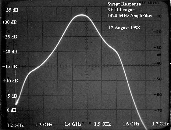
The swept frequency response of the completed AmpliFilter prototype is seen in Figure 4 below. Note that potentially interfering signals from GPS satellites at 1575 MHz are attenuated by about 20 dB, and that 1620 MHz interference from the swarm of 66 recently launched Iridium satellites is reduced by over 30 dB. If this AmpliFilter is placed ahead of a receiver using a 144 MHz IF, an additional 40 dB to 50 of image rejection will be realized.
Because microstrip filters are inherently low-Q devices, it may still be necessary to use a high-Q cavity filter if your SETI station operates in areas of high electromagnetic interference.
|
 SETI League photo |
email the Webmaster | entire website copyright © The SETI League, Inc. this page last updated 4 January 2003 |
Top of Page |