 Publications Department
ABSTRACT
The parabolic reflector has, since the days of Reber, been the antenna of choice for amateur radio astronomers. Project Argus participants are no exception, typically employing discarded backyard satellite TV dishes of three to five meters in diameter. Such antennas perform well, but their size, as well as complications of municipal zoning restrictions, preclude their use by many a potential Argonaut.
This article presents construction and performance details of an alternative Argus antenna, a portable waveguide horn reminiscent of the one used by Ewen in 1951 to first detect the 21 cm radiation signature of interstellar hydrogen. Producing +19 to +21 dBi of gain across the 1200 - 1700 MHz band, the SETI Horn of Plenty rises to the challenge of mapping galactic hydrogen. It also performs well in monitoring the Sun, the Moon, natural radio sources in Cygnus, Cassiopeia, Taurus, and Sagittarius, and (maybe, some day) in detecting ETI.
INTRODUCTION
Project Argus, a major scientific endeavor of the nonprofit SETI League, Inc., is an attempt to coordinate a global network of amateur radio telescopes in conducting an all-sky survey for microwave emissions of intelligent extraterrestrial origin. Though the holy grail of SETI (the Search for Extra-Terrestrial Intelligence) remains the detection of unambiguous evidence of other technological civilizations in the cosmos, Project Argus participants are also applying their amateur radio telescopes to the challenges of studying natural astrophysical phenomena through their microwave emissions.
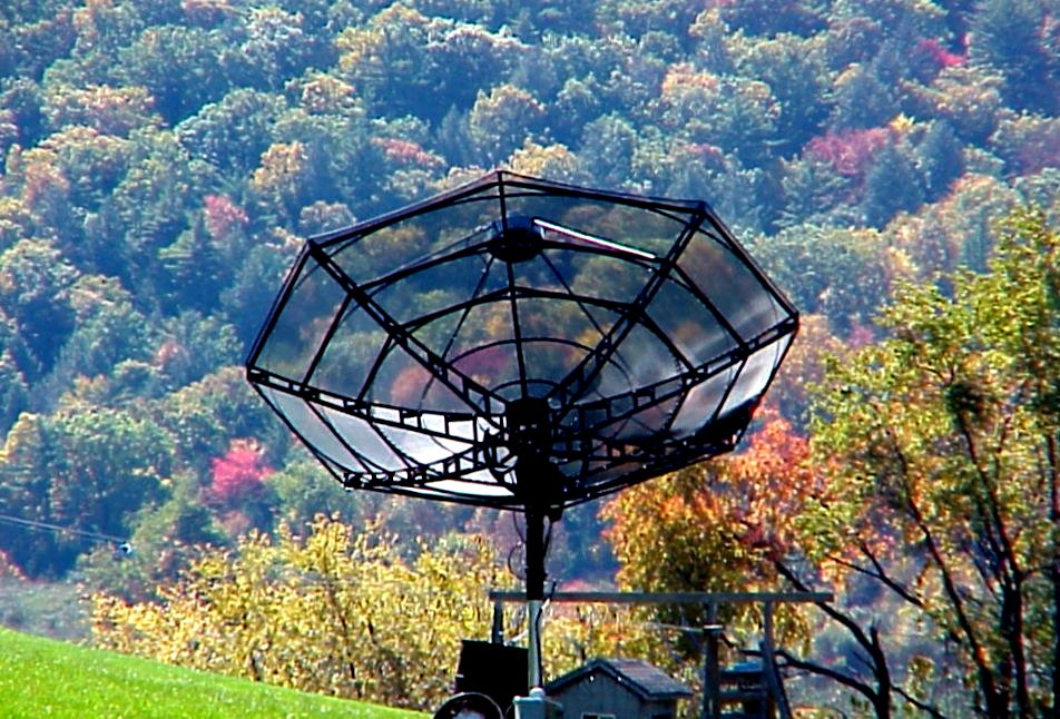
The typical Project Argus station is designed around surplus C-band satellite TV antennas of three to five meters in diameter [1], such as the one depicted in Figure 1.
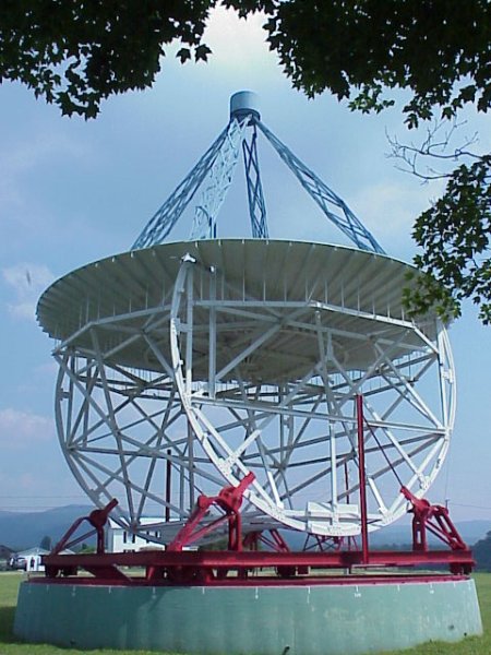
Parabolic reflectors have been the antenna of choice for amateur and professional radio astronomers alike since the 1930s, when the late Grote Reber, W9GFZ, constructed a ten-meter diameter dish in the back yard of his mother's house in Wheaton, IL (see Figure 2), and used it to produce the first radio maps of the Milky Way Galaxy.
Unfortunately, though Project Argus has achieved widespread participation by hundreds of radio amateurs in dozens of countries, it falls far short of its ambitious goal of real-time all-sky coverage, which would require the coordinated efforts of 5,000 participating stations, properly dispersed around the globe. One barrier to participation for many a perspective Argonaut is the physical structure of the required antenna. These dishes are arguably large and unsightly, and where physical constraints do not preclude their installation, local zoning ordinances often do. Thus, there exists a need for more compact, portable antennas, which can be deployed on demand by those amateurs interested in pursuing radio astronomy and SETI.
In the L-band radio spectrum favored by many amateur radio astronomers, the typical backyard parabolic dish exhibits in excess of +30 dBi of gain. Meaningful research, however, can be done with antennas exhibiting perhaps 10 dB less gain. Since the parabolic reflector is a non-resonant, low Q structure, it can be made to operate over a wide range of frequencies. Any alternative to the parabolic dish must similarly be capable of operating over a reasonably broad bandwidth.
Thus, it is our goal is to develop a readily transportable antenna of +20 dBi gain, which covers a reasonable portion of that frequency spectrum of the greatest interest to amateur radio astronomers. A likely contender is the waveguide horn antenna.
HORN HISTORY
The first real microwave gain antenna was a cylindrical parabola developed by Heinrich R. Hertz in 1888. Hertz wrote, "As soon as I had succeeded in proving that the action of an electric oscillation spreads out as a wave in space, I planned experiments with the object of concentrating this action and making it perceptible at greater distances by putting the primary conductor in the focal line of a large concave parabolic mirror." [2]
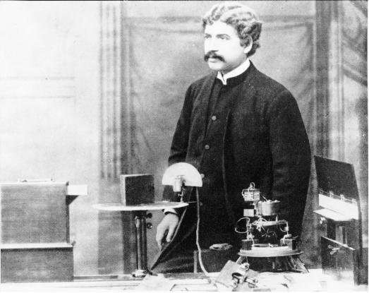
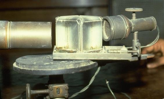
In 1894, Sir Oliver Lodge first demonstrated waveguide microwave transmission lines at London's Royal Institution. Three years later at the University of Calcutta, Indian physicist J.C. Bose (seen in Figure 3) flared out the end of a waveguide, demonstrating the horn antenna seen in Figure 4. Being a low-Q structure, the Bose horn offered respectable gain over perhaps an octave of bandwidth.
Numerous experimenters, including Marconi (who in 1897 recovered microwave communications over a four-mile path in a demonstration for the British post office), employed waveguide horn antennas. But it was not until 1951 that this promising antenna configuration was applied to the challenges of radio astronomy.
REVERSE ENGINEERING EWEN
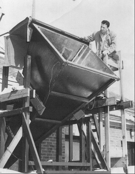
In one of radio astronomy's landmark experiments, Harvard University graduate student Harold I. "Doc" Ewen built the horn antenna seen in Figure 5, to first measure the 1420 MHz hyperfine transition line of interstellar hydrogen [3]. He based his antenna design on the earlier work of University of California professor Samuel Silver at the MIT Radiation Laboratory [4], with its physical dimensions constrained by the size of the parapet in Harvard's Lyman laboratory where his receiver apparatus was installed. This horn is now on display, along with Grote Reber's dish seen in Figure 2, at the National Radio Astronomy Observatory, Green Bank WV. Since Green Bank is the site of the annual meeting of the Society of Amateur Radio Astronomers (SARA), it is safe to say that these two antennas have inspired a whole generation of amateur radio astronomers.
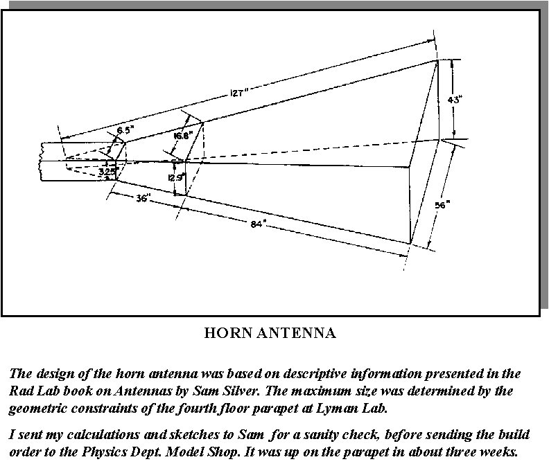
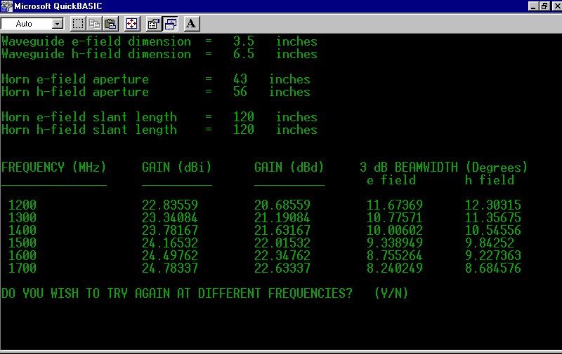
The radiation characteristics (gain and beamwidth over frequency) of a pyramidal waveguide horn are purely a function of its physical dimensions. Ewen thoroughly documented the physical dimensions of his horn (see Figure 6), which allows us to reverse-engineer its performance. I did this analysis using a Microsoft Basic program which I published fourteen years ago [5]. The resulting computed gain, e-field beamwidth, and h-field beamwidth at L-band are shown in Figure 7.
SCALING THE EWEN HORN
These calculations reveal that Ewen's horn exhibited a gain just under +24 dBi at the hydrogen line, with a nearly symmetrical pattern producing a half-power beamwidth on the order of ten degrees in both the e-field and the h-field. A replica of the Ewen horn would thus seem to provide ideal performance for an amateur radio telescope, but for its size. The horn length of ten feet is definitely unwieldy, and provides little advantage over the standard satellite TV dish we are attempting to replace.
It was decided to scale the dimensions of the Ewen horn, in search of a reasonable compromise between performance and size. A somewhat arbitrary horn length of four feet, and width of three feet, were selected, constrained by the standard size of available materials (26 gauge galvanized sheet steel is readily available in 3 foot by 4 foot sections, at under $10 per sheet from a local fabricator of heating, ventilation and air-conditioning ductwork.)
Scaling all remaining dimensions to the selected horn width and length, and retaining the same L-band waveguide dimensions used by Ewen, allowed us to determine preliminary design dimensions of the SETI Horn of Plenty. The resulting performance was analyzed in software (see Figure 8). Gain comes in at 3 to 4 dB below the Ewen horn, with symmetrical beamwidths of 16 degrees in both planes.
TONY'S DISPOSABLE HORNS
At the 2002 Amsat Space Symposium, Anthony Monteiro, AA2TX, demonstrated a technique for manufacturing disposable horn antennas of negligible cost, out of corrugated cardboard, aluminum kitchen foil, and packing tape [6]. One of Tony's antennas, used for 2.4 GHz satellite reception, is shown in Figure 9, and was an inspiration for the SETI Horn of Plenty.
Unfortunately, cardboard and foil proved insufficiently robust for our purposes, and we had to resort to 26 gauge galvanized sheet steel. In email correspondence with the author, Tony opined, "I agree that while cardboard is fun and a neat demo, for a serious radio telescope, the metal antenna is the way to go. After all, what if ET calls and it is raining that day?"
CONSTRUCTION DETAILS
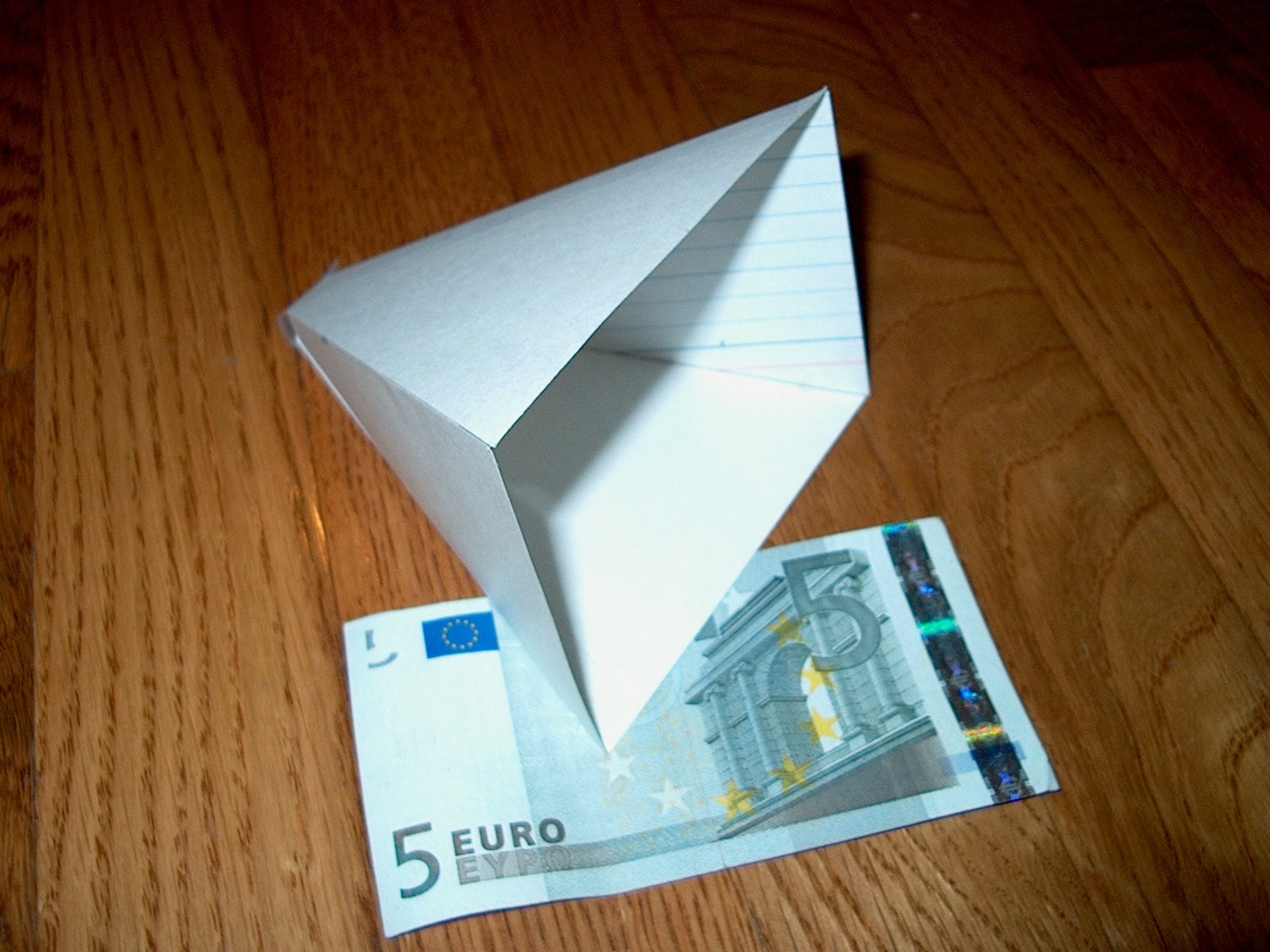
Whereas cardboard construction is inadequate to our purposes, it provides us with an easy way to verify that all the pieces are going to fit together, before we take shear or tin snips to ten dollar sheets of steel. It is not, however, necessary to build a full-size model in order to determine goodness of fit. Since the largest piece of metal in the proposed design measures three by four feet, it's a simple matter to scale the design by a factor of twelve, and mock it up out of 3-inch by 5-inch index cards. The result of this exercise, seen in Figure 10, affirms the compatibility of the proposed dimensions.
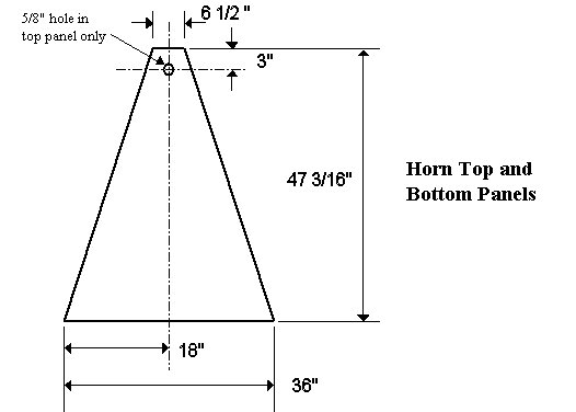
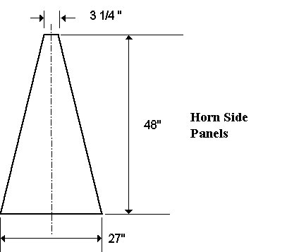
The four sides of the truncated pyramid, dimensioned according to Figure 11 and Figure 12, were fabricated at the local sheet metal shop in a matter of minutes. Figure 13 shows the quarter-wavelength monopole probe used to excite the horn, fabricated out of a Type N flange mount coaxial connector and a length of brass hobby tubing. The four horn sections are joined to 1" wide by 1/8" thick aluminum angle stock (sold locally at 75 cents per foot) with pop rivets. I like to place the pop rivets about a quarter wave apart at the operating frequency, which equates to about two inch spacing. Don't forget to rivet a 3 1/4" by 6 1/2" sheetmetal short at the back of the horn.
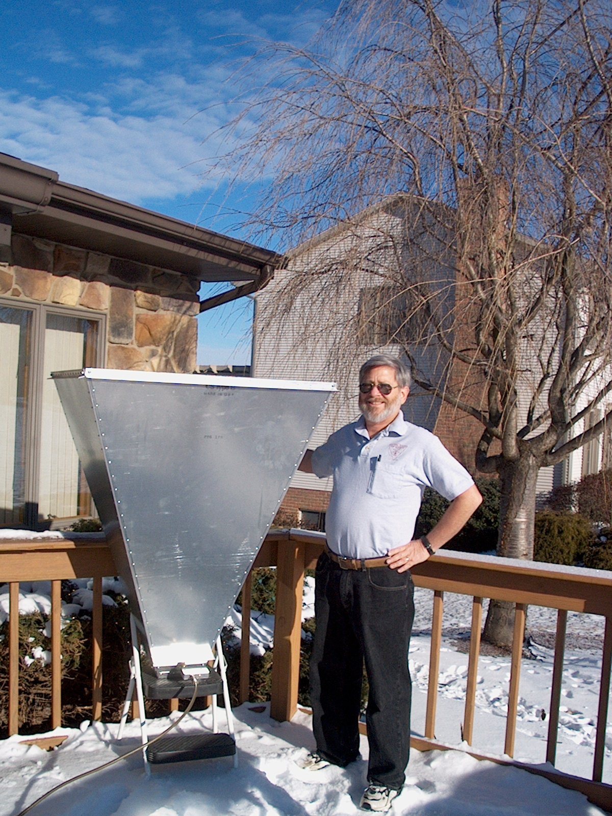
The completed SETI horn prototype is seen in Figure 14, undergoing testing.
PERFORMANCE
Although this horn antenna suffers a three to four dB gain deficit when compared to the Ewen horn, today's receivers are at least ten dB more sensitive than the simple diode mixer design used by Ewen a half century ago. Thus, the Horn of Plenty is entirely capable of detecting interstellar hydrogen radiation, as well as a number of astrophysical thermal sources. It would quite easily have detected the famous Ohio State University "Wow!" signal [7], suggesting its value as a SETI antenna. It can be used to monitor communications and navigation satellite activity in L-band, to recover amateur signals reflected off the lunar surface at 1296 MHz, and to perform radio frequency interference surveys. These are valuable scientific endeavors, whether or not the horn ever captures ET's call.
This horn design exhibits gain on a par with that of a quad helix array, a single long yagi, or a one-meter dish. However, the horn's excellent broadband impedance match, inherent lack of overspill, and low sidelobes mean its ground noise pickup will be significantly less than that of alternative antennas, providing a greater signal to noise ratio than one would expect from gain figures alone.
CONCLUSION
A waveguide horn antenna has been introduced, which acquits itself well in radio telescopes operating across the entire Water Hole frequency spectrum. Its advantages over a parabolic dish are extremely low cost, ease of fabrication from locally available materials with common hand tools, portability, and zoning compatibility. Its performance, though arguably marginal for SETI, is still adequate for reasonable amateur radio astronomy, in that it can successfully detect the six strongest natural astronomical radio sources, clouds of interstellar hydrogen, half a dozen classes of orbital satellite, and moonbounce signals in the 23 cm amateur band. Whether our cosmic companions can radiate sufficient power to make themselves detectable with such an antenna remains to be demonstrated.
REFERENCES
See additional Construction Photos
email the Webmaster | entire website copyright © The SETI League, Inc.; Maintained by Microcomm this page last updated 5 February 2005 |
Top of Page |